

ROLE OF GROUNDING IN ELECTRICAL SAFETY – Design, Compounds & Myths
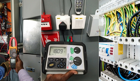
The visible components of the electrical system, such as Earth Electrodes, are successfully addressed by general maintenance practices. The Grounding System suffers from the "OUT OF SIGHT, OUT OF MIND" issue because the majority of it is buried beneath and unreachable.
A complete grounding system, including the Equipment Earth Conductor, Earth Electrode, and Earth Grid/Mat, should provide a low resistance path for fault current to flow, allowing breakers to trip in time to avoid incidents such as fire, short circuit, and electric shock.
One common misconception is that if the measured overall earth resistance value is 1 Ω or less, the grounding system is safe. However, resistance of 1 Ω is NOT AT ALL indicative of the grounding system's safety or health.
Low Earth Pit Resistance ≠ Safety. Whereas Low Earth Loop Impedance = Breaker Tripping on time = Safety.
The grounding system's principal purpose is to allow enough current to flow through the earth fault loop so that the protective device can detect a possible fault and isolate the damaged circuit in a reasonable amount of time. The magnitude of current that will flow through the earth loop in case of a fault depends on the impedance of the earth fault loop.
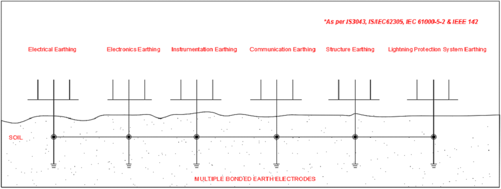
Another myth revolves around the concept of Global Grounding. As per the concept of "Global earthing", electrical earthing, electronic earthing, instrumentation earthing, communication earthing, structure earthing and lightning protection system earthing should be interconnected below the ground. This is recommended in IS 3043, IS/IEC 62305, IEC 61000-5-2, and IEEE 142 Standards.
Grounding System Design
An important aspect in today's complicated electrical systems is to have a robust and optimal design solution. The best techno-economic solution in the design of grounding systems is only possible through Multi Layer Soil Modeling and computer-aided designs involving high-end technical software such as CDEGS.
Grounding Compound
According to IEEE 142, the Backfill compound affects the crucial region around the electrodes. The grounding system's long-term reliability is determined by the type and quality of the backfill compound. IEEE/BS standards recommend using ground enhancement material or conductive concrete with a resistance of less than 0.12 Ohm meter surrounding the electrodes for enhanced long-term stability. The carbon-based ground improvement compounds are long-lasting and don't leach chemicals into the soil.
Indian & International standards recognize that treating an area of about 75 to 100 mm surrounding the Electrode with ground enhancement materials will significantly reduce the earth resistance, generally in the region of 25 to 40%. The IEC 62561-7 for backfill compound recommends a series of tests to ensure the compounds do not contain any harmful chemicals. It is also important to test these compounds for conformity to ANSI/NSF 60 standards since 40% of the water requirement in India is met from ground water.
Please let us know if you need further assistance or have any requirements: [email protected]


