Application Note: Lightning protection & Surge protection requirement for Wind Turbines as per IEC 61400-24.
A windmill is a device that uses sails set on a spinning shaft to harness the energy of the wind.The panels are rigged at an angle or with a slight twist, splitting the wind force into two components, one of which causes rotation in the sails' plane.
India’s economy is growing rapidly in a vibrant mode and in an efficient way, which in turn demands huge uninterrupted energy supply. Utilization of regenerative energy is on a steady rise over the past two decades. Windmills, Solar PV & bio-gas plants are getting popular day by day. This high market potential is not only for the energy sector but are equally available for the Electrical & Electronic equipment suppliers worldwide.
In this application note, let us talk about windmills, which are megawatt plants. The buy-back period is only a few years, and any stoppage will have a crucial impact on the return on investment, downtimes are expensive for owners of such high-value installations.
IEC 61400-24: Lightning Protection of Wind Turbines is the basis for the solution.
There are two common challenges for the windmills.
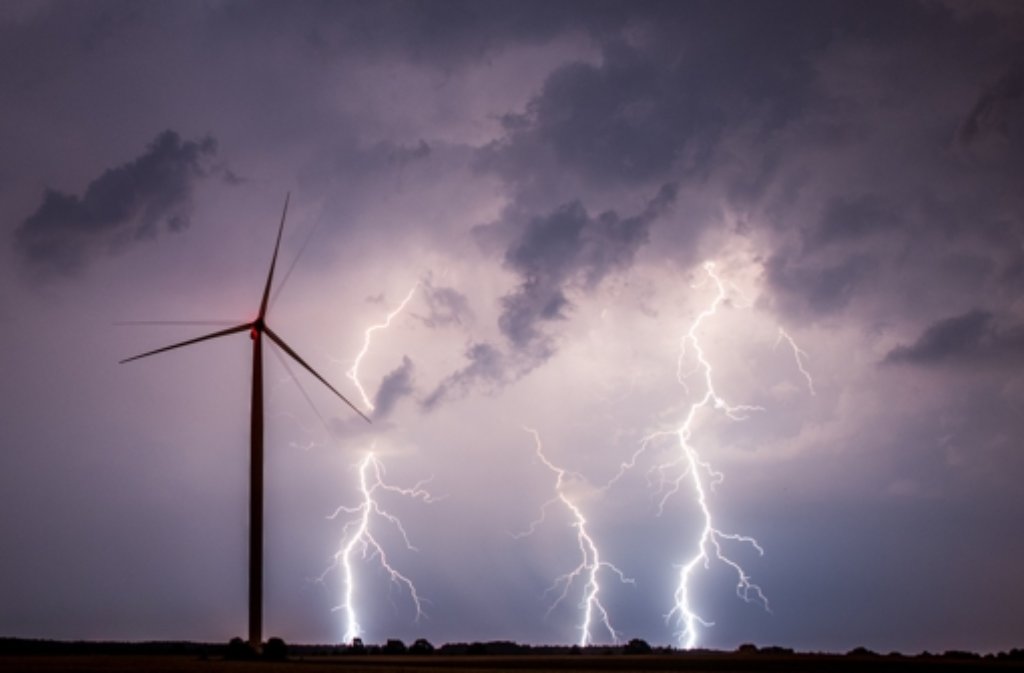
1-They are much taller than the surrounding environment (100 m & above)
2-The concentration of electrical & electronic system is confined in a small area
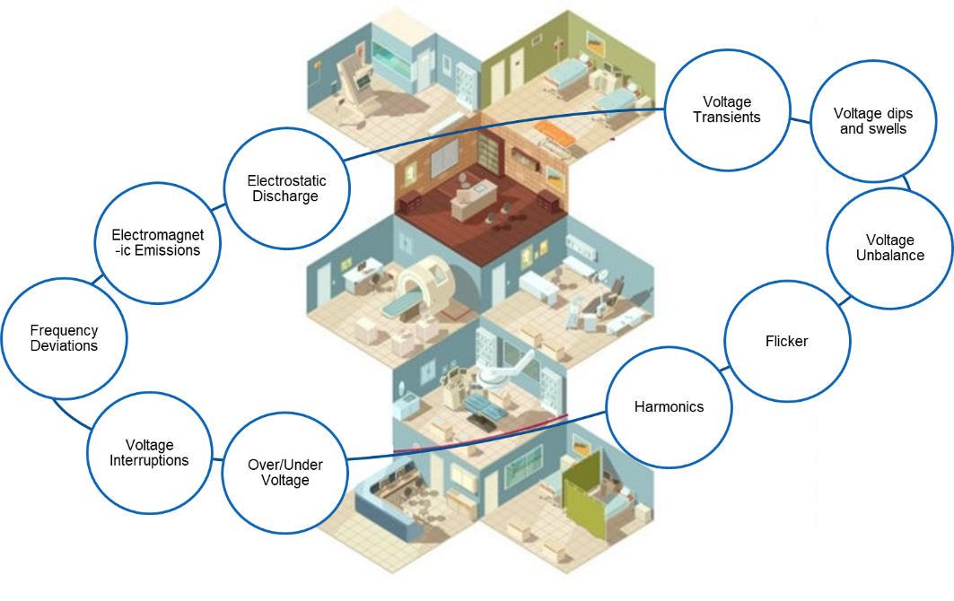
The electrical & electronic system includes switchgear cabinets, motors, drives, frequency converters, actuators, sensors, control electronics including communication bus systems employing Modbus or Profibus protocol via RS 485 physical layer of popular ISO/OSI 7-layer model are followed worldwide.
Lightning surges from Mother Nature & switching surges from radiation or generated internally & propagated through metallic structures pose a huge problem to windmill electronics as “height” of the windmill and exposed nature of installation plays an important role in inviting surges.
The annual number of lightning strikes (cloud to ground) is determined from isokeraunic level. NBC 2016 also has this data for major Indian cities. As windmills are taller than 100 m, upward flashes in the form of ground to cloud flashes is also a possibility, apart from cloud to ground flashes. In addition, ground to cloud flashes starting from high exposed objects carry higher charges of lightning current because of which, due importance has to be given to the protection measures of rotor blades apart from suitable SPD measures.
Shielding procedures and a global earth termination system are critical for the protection of electronics inside windmill Lightning protection zone designs, ensuring that the entire system runs inside a predetermined EMC (Electro Magnetic Compatibility) environment.
LPZ (Lightning Protection Zone): This is a concept in which conducted and radiated interference are gradually reduced from coarse to choice(sensitive) electronics using SPDs and LPS in the form of a Faraday cage. Ensuring that the voltage withstanding level of each piece of equipment never exceeded, even in the event of a lightning strike. This is accomplished using the "insulation coordination strategy," in which each entry-level SPD uses shielding strategies to protect the next-level SPD. In addition to safeguarding the electrical and electronic equipment in their zone. There are four Lightning protection zone in windmill systems.
LPZ O A : The area above the LPS installation (electric & magnetic field are maximum)
LPZ O B : The area just below the external LPS which is covered by rolling sphere radius. (first level of attenuation)
LPZ 1: Entry point of power & signal cables from the windmill tower to the building. (second level of attenuation)
LPZ 2: Place where sensitive electronic equipment is located. (final level of attenuation where electric & magnetic fields are very minimum and will be unable to cause any upset to the equipment)
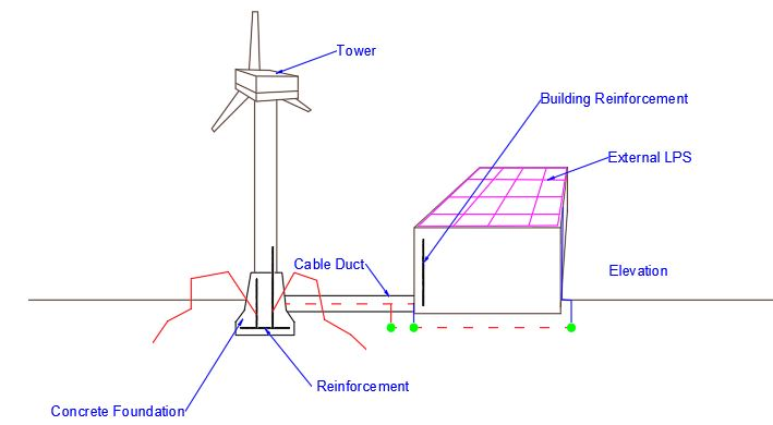
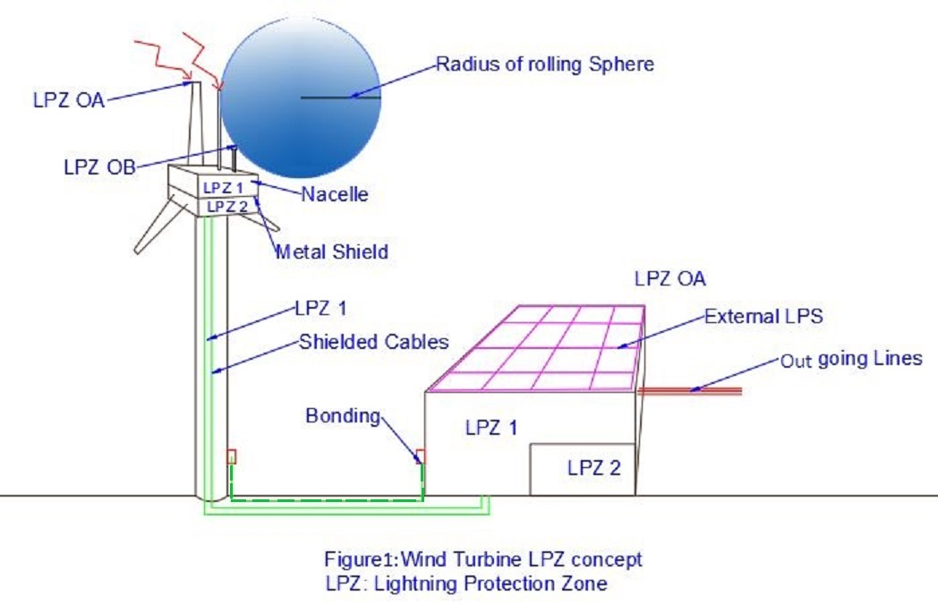
Figure 1: Wind turbine LPZ concept
Shielding: Nacelle are made of metal which is a closed structure by itself to protect from radiated effects of lightning. The attenuation of EM field is maximum inside this closed metal volume when compared to high level of EM field outside the metal surface. Switchgear and control cabinets are also made of metal for the same purpose. Shielded cables shall be used which has 360-degree bonding at entry & exit points which is connected to EBB (Equipotential Bonding Bar) on either side of the cable. EBB is referred as MET- Main Earthing Terminal in IEEE standards.
Earthing: “Global earthing” as explained in the IS3043 latest edition (2018) shall be followed which includes the structural steel reinforcement of wind turbine with the earth grid surrounding the wind mill & the building, which is located outside the windmill.
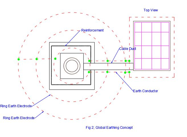
Figure 2: Global earthing concept.
SPDs: While radiated surges are limited by shielding technique, conducted surges are reduced below the withstanding level of equipment by using SPDs for power, data, and communication lines.
Either Class I or Class I+ II 3 phase SPD with 400/690 V compatible with minimum Iimp of 12.5 kA for TN-C system shall be employed in parallel at the main DB taking care of the installation technique strictly recommended as per the Installation
Instruction of SPD manufacturer. TN-C system is one, in which neutral & protective earth are combined to form PEN, which is 4 wire system (R, Y, B & PEN). SPD shall have local & remote indication in the form of relay contact with NO/NC points which can be connected to hooter or LED or as a contact input of the PLC system.
For more information, contact us at [email protected]"