IMPORTANCE OF SOIL RESISTIVITY IN THE DESIGN OF EARTHING FOR THE SAFETY & RELIABILITY
Soil resistivity is a measurement of the resistance or electric current that the soil conducts.The design of a system based on passing current across the surface of the earth is a key component.
Soil resistivity plays a vital role in the design of an earthing system. For substations, the key design acceptance (safety) criteria of touch and step potentials soil resistivity are greatly influenced. For othergrounding systems such as industrial plants / commercial and residential buildings, the acceptance criteria of overall grounding resistance and current density on the electrode surface are also dependent on soil resistivity. Hence, the accuracy of the design depends on the accuracy of the measured Soil resistivity values.
As per standards, the soil conditions up to 3 to 4 times the longest dimension of the mat affect the current dissipation. The soil generally is not uniform all through the depth & breadth and varies with topography.
Soil resistivity can be measured in a variety of methods. Electrical profiling is the best approach for assessing soil resistivity for the design of earthing and safety requirements. By injecting a current, and monitoring the voltage drop at different spacing, without any excavation electrical profile of the soil can be done. Wenner's Four-Point Method is the most popular and user-friendly method.
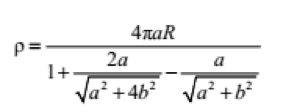
In Wenner Four point method the resistivity is measured by using four spikes with equal spacing connected to the soil resistivity meter. The extreme spikes are called as current spikes and the inner spikes are called as potential spikes. The current will be injected through the extreme spikes. There will be a potential gradient in the mean area and the drop in the potential is measured between the potential spikes. The meter will display the resistance which can be used for the interpretation of resistivity of the soil by the established formula.
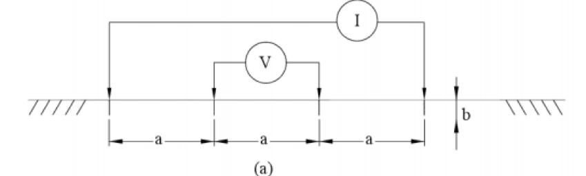
As the variation of depth is invariant with the spacing, the simplified form of the above formula would be
Further, the resistivity of the soil cannot stay uniform all throughout the life as the soil can be eroded due to wind, rain, floods, manmade actions (excavations) etc. So the earth pit resistance cannot be compared with the measured resistivity during the design /construction phase and the evaluation should be done by measuring the resistivity of the soil along with the measurement of the earth pit resistance at the time of acceptance testing.
The resistivity of the soil normally varies for the different layers. As we go deeper, the resistivity of the soil may not vary much seasonally / changes in environmental conditions. Hence, the variation in resistivity of the top layers needs to be considered for earthing design.
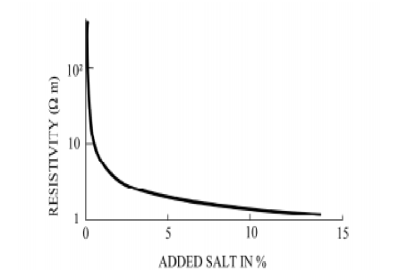
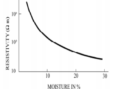
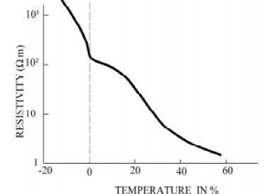
The resistivity of the soil is dependent on salt content, moisture and temperature and varies as per the graph below.
Parameters impacting the soil resistivity measurement
Soil resistivity measurement should be carried by using a quality meter which complies with the international standards and as per IEEE 81 Annex E. The measurement is to be carried by a meter which is having a capability of injecting the current at variable frequency and with variable voltage. The readings measured with low quality meters will not show accurate readings. Factors affecting measurement are:
- Presence of loose/backfilled soil
- Presence of any buried metals like water, gas, other process pipelines and cables.
- Presence of live HT lines above the test setup may have an induced current in the cables connecting the spikes and may result in errors in measurement and also potential hazard to the personnel working on the test setup.
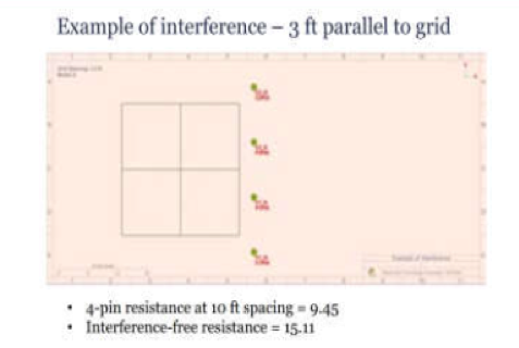
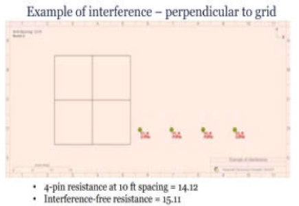
- Presence of water table near the measurement area or presence of any earth gird of a substation will have an impact on the measured values.
- To obtain accurate measurement, the distance of any such earth grids and water table from the soil resistivity measurement area should be at least the spacing between the spikes.
Soil resistivity cannot be considered based on the average of values for the varying depths.
Readings should be measured at different depths in a given direction and compared with the previous reading of the same direction to check the extent of variation. If there are any abnormal variations in the readings, the measurements may be repeated / additional measurements done for the intermediate depths. Typically, the largest variation in a given direction should be less than 30% for the soil to be considered as uniform.
If variation is beyond this limit (which is true in most cases), the soil is deemed to be non uniform and multilayer soil model shall be used for designing. The number of layers will depend on the measured values and the criteria shall be to have as close match as possible with the measured values (As low an RMS error as possible).
While using a simple average (arithmetic mean) of measured soil resistivity values for design, the margin of error in safety parameters due to soil resistivity can easily exceed 100%.
The standards have provided formulas to determine approximate values of touch and step potentials for uniform layer and two layer soils and for multi-layer soil it is necessary to go in for software simulation models as prescribed in the IEEE 80 Annex H. The CDEGS software by SES has multi layer modelling capability and provides accurate and optimum design with least possible error.
Measurement of resistivity at a location should be done depending on the function / purpose of the proposed earthing system. If standard earth pit of 3mtrs are to be installed (normal industrial plants, commercial / residential buildings), then the soil resistivity of upto a depth of 10mtrs is required. For a substation grid, the resistivity to a depth not less than the length of diagonal of the grid should be measured.
Hence, an accurate measurement of soil resistivity is important in ensuring an optimum grounding design.
For more information, contact us at [email protected]"