The visible components of the electrical system, such as Earth Electrodes, are successfully addressed by general maintenance practices (Pits). The Grounding System suffers from the "OUT OF SIGHT, OUT OF MIND" issue because the majority of it is buried beneath and unreachable.
Equipment Earth Conductor (Strip), Earth Grids / Mats, which are underground or inaccessible, are often taken for granted or overlooked, although they are critical. The grounding principle is one of the most widely discussed issues in the electrical system, although it is riddled with misconceptions and fallacies.
A complete grounding system, including the Equipment Earth Conductor, Earth Electrode, and Earth Grid / Mat, should provide a low resistance path for fault current to flow, allowing breakers to trip in time to avoid incidents such as fire, short circuit, and electric shock.
One common misconception is that if the measured overall earth resistance value is 1 or less, the grounding system is safe.
However, it is important to remember that resistance of 1 is NOT AT ALL indicative of the grounding system's safety or health.
Low Earth Pit Resistance ≠Safety Whereas Low Earth loop Impedance = Breaker Tripping on time= Safety.
Irrespective of the measured value, the resistance of the earth pits can never indicate the healthiness of the grounding system or otherwise.
The grounding system's principal purpose is to allow enough current to flow through the earth fault loop so that the protective device can detect a possible fault and isolate the damaged circuit in a reasonable amount of time.
The magnitude of a current that will flow through the earth loop in case of a fault depends on the impedance of the earth fault loop. (The earth fault loop comprises of the path from the connected phase conductor of the equipment to the grounding system and the source neutral).
As a result, it is critical to monitor the earth fault loop impedance and keep it low enough for the protective devices to activate and isolate the fault in the event of a fault.
EARTH LOOP IMPEDANCE TEST for star-connected low and medium voltage systems is required to achieve this. A prospective fault current test can also be used to determine if the protective device's rating is appropriate. For the systems mentioned above, these stages automatically check the integrity of the buried segment of the earth conductor loop.
Specific riser and earth grid integrity tests are required for EHV substations and other LV, MV, and HV installations with a large earth grid/earth mat to ensure the integrity of the earth connections buried in the soil. The integrity of a double earth connection to every structure and piece of equipment in the substation is tested with a riser integrity test.
The current division and voltage drop are checked by introducing a tiny current through the grounding system at off-grid frequency. Because they can pinpoint the problematic connections/risers in the subsurface grounding system, these procedures are particularly effective.
Both the above tests can be done on live electrical systems without calling for the shutdown.
Another myth revolves around the concept of Global Grounding As per the concept of “Global earthing”, electrical earthing, electronic earthing, instrumentation earthing, communication earthing, structure earthing and lightning protection system earthing, should be interconnected below the ground.
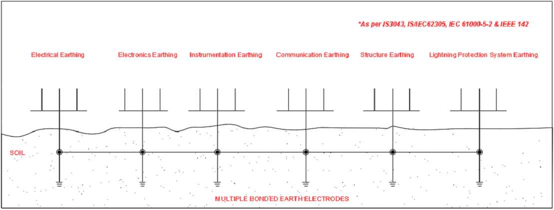
The Concept of isolated earth electrode is not relevant for electronic and instrumentation systems since there are always links with other earth electrodes through (a) soil and (b) through parasitic elements - example capacitance and mutual inductance. Also during lightning or power system fault high transient over voltage develop between this “isolated” earthing system and other parts of the installation which is dangerous for equipment safety, personal safety and electromagnetic compatibility (EMC).
"Connecting all earthing system together is also confirmed by Central Electricity Authority - CEA in its 2016 draft version "Periodic comprehensive review of the CEA (Measures relating to Safety and Electric Supply) regulations, 2010 (as amended) as below under regulation 37 - Conditions applicable to installation of voltage exceeding 250 Volts and more detailed under regulation 41 - Connection with Earth for systems exceeding 48 Volts and not exceeding 650 Volts. The above concept is recommended in IS 3043, IS/IEC 62305, IEC 61000-5-2,IEEE 142 Standards.
Grounding System Design
Another important aspect in today’s complicated electrical systems is to have robust and optimal design solution. And to get the best techno-economic solution in the design of grounding systems is only possible through Multi Layer Soil Modeling and computer-aided designs involving high end technical software’s like CDEGS.
With the advent of technology, computer-aided software designs of grounding systems have assumed greater importance and significance. In-depth analysis , better accuracy, optimization without compromising accuracy are the hallmarks of computer software-CDEGS Software based design.
Grounding Compound
At Last but not the least comes the quality grounding compounds & components and finally the installation by professionals.
According to IEEE 142, the Backfill compound affects the crucial region around the electrodes. Hence, the technology to obtain a successful grounding is dependent on it. The grounding system's long-term reliability is determined by the type and quality of the backfill compound. IEEE/BS standards recommend using ground enhancement material or conductive concrete with a resistance of less than 0.12 Ohm meter surrounding the electrodes for enhanced long-term stability. The carbon-based ground improvement compounds are long-lasting and don't leach chemicals into the soil.
Indian & International standards recognize, that, treating an area of about 75 to 100 mm surrounding the Electrode with ground enhancement materials having low resistivity will significantly reduce the earth resistance, generally in the region of 25 to 40%.The IEC 62561-7 for backfill compound recommend a series of tests to ensure the compounds do not contain any harmful chemicals.
However, it is also important to test these compounds for conformity to ANSI / NSF 60 standards since 40% of the water requirement in India is met from ground water and hence, it is very important, the backfill compound used for earthing system does not pollute the underground water resources.
Conventionally, for earthing, a cast iron plate / GI pipe is used as an electrode. The pit is excavated and the electrode is placed in the centre and is filled with soil, mixed with salt and charcoal. The conduction of current in the conventional electrode is electrolytic. Hence, regular watering and charging of the earth pit with salt is very essential to maintain low earth resistance.
Moisture plays a very crucial role in the resistance of the electrode. India being a tropical country, where close to 9 months is dry season, making necessary provision for watering as recommended in Indian standards is challenging. Even to raise the moisture content to 5% in dry season, a single earth pit needs around 4000 liter of water which is impossible to provide with so much scarcity.
Watering an electrode and charging with salt is obviously not done on a regular basis due to these practical limits, and the salt provided dissolves over time due to rain (in many places, within 2-3 years). As a result, the resistance rises and the grounding becomes useless.As a result, it is best to opt for Grounding Solutions that don't require any maintenance. Treatment of the soil surrounding the electrode's critical area allows for maintenance-free grounding.
For more information, contact us at [email protected]"