LOW VOLTAGE SPD- SELECTION & INSTALLATION - MYTHS VS FACTS.
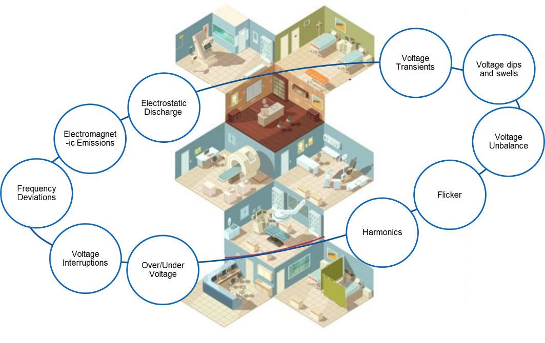
Low voltage is defined as any AC RMS voltage up to 1000 V or DC peak voltage up to 1500 V. This needs to be kept in mind because Medium voltage SPD- called as LA- Lightning Arrestor manufacturing techniques, selection and installation is totally different from low voltage SPDs
In general,
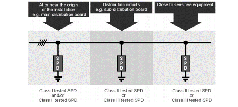
SPDs need to be installed at main DB, sub DB and at equipment level as per Figure 1.
Low Voltage SPD- Selection & installation
Figure 1-Example of installation of Class I, class II and class III tested SPDs
In the above figure instead of Class I and Class II, Class I + II can be used if Iimp value is taken care
It is because SPDs provide an “effective” protection distance of a maximum of 10 meters. It means, if the distance between the SPD and the equipment to be protected is greater than 10 meters, additional SPDs will be required. The crucial point to note in this case is that the “actual” wire length needs to be calculated rather than the physical distance between the SPD and equipment.
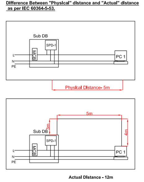
Figure 2- Difference between physical distance and actual distance.
Physical location of equipment is important to select the quantity of SPDs. In the below Figure 3- 2 examples are given. In Example1, the number of PCs are 5 & in Example 2, the number of PCs are 4.. But in Example 1, one SPD is enough to protect all the 5 PCs as the “actual ‘ distance from SPD to the farthest PC- PC 3 is only 5 meters, because all the PCs are kept in one room, next to each other. Whereas. In Example 2, 4 number of SPDs are needed to protect 4 PCs , because 1 PC is located in each floor and the ‘actual” distance exceeds 10 m in Floors 1, 2 & 3.Only PC 1 does not require any additional SPD because the “actual’ distance from the SPD which is in Sub DB is only 5 meters away from PC1.
Fig 3-Example 1
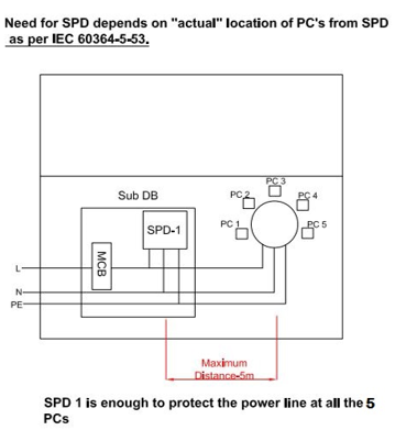
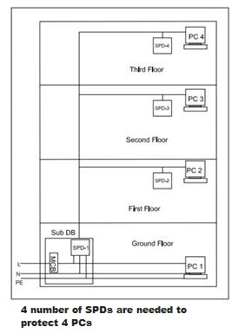
Figure 2- Difference between physical distance and actual distance.
The below selection principle shall be strictly followed:
a) Protection between Live conductor and PE is COMPULSORY.
b) Protection between Live conductor and neutral is RECOMMENDED to ensure equipment protection.
c) Protection between Live Conductors ( 3 phase) is OPTIONAL.
Selection - MYTH:
Few SPD manufacturers strongly recommend costly SPDs assembled in big Stainless steel enclosures to protect critical installations without any back up from IEC standards. It is clear from the above recommendation that. Protection between Live Conductors is OPTIONAL.
Installation of three-phase LV SPD in 2-connection types- CT-1 (Connection Type 1) & CT-2 (Connection Type 2). In Connection Type, CT 1, TWO types of earthing arrangements are possible i.e., L1, L2, L3, N & PE (i.e., neutral and earth are separate wires & termed as N & PE) and L1, L2, L3 & PEN (i.e., Neutral and Earth are combined as one wire & termed as PEN). Only one sort of earthing arrangement is possible in Connection Type CT-2. There was previously some misunderstanding over whether to use CT1 or CT2, as both the IEC standard suggested.
Selection - FACT:
In September 2015, the latest IEC standard, IEC 60364- 5-53 (Edition 3.2), was published. Electrical Installation of Buildings- Part 5-53- Selection and erection of electrical equipment- Isolation, switching, and control clearly outlines the concepts of LV SPD selection and installation.
The CT-1 connection type big protects against common-mode attacks. (For example, between the Live and Neutral endpoints and the Neutral and Earth terminals). Concisely, PE is protected between L and N.
The CT-2 connection type combines common-mode and differential-mode protection (i.e., between the Live and Earth terminals) (i.e., between Live & Neutral terminals).
The above explanation can be easily understood from the below 3 figures.
The above explanation can be easily understood from the below 3 figures.
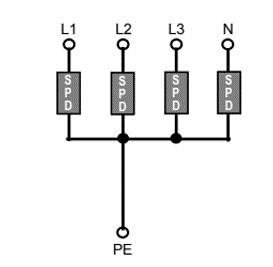
Figure- 4 -Connection type CT1 (4+0 configuration) for a 3 phase system with separate neutral and earth terminals (Common mode protection)
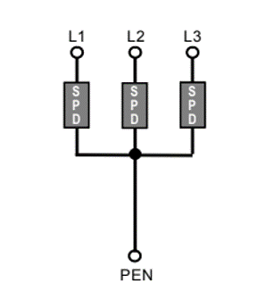
Figure- 5- Connection type CT1 (3+0 configuration) for a 3 phase system with combined neutral & earth terminal (Common mode protection)
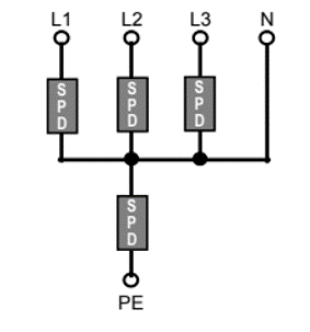
Figure- 6- Connection type CT2 (3+1 configuration) for a 3 phase system with separate neutral & earth terminal (Common & Differential mode protection)
Please note that, if you observe closely, Connection Type CT2 is not possible for PEN- I.e combined Neutral & Protective earth, because if N& PE are combined, it automatically becomes CT 1 (3+0) configuration.
Only connection type CT-2 need to be followed, due to the constraint in Voltage Protection level and the installation bottleneck. (explained in the next section)
Installation - MYTH:
In some installations, the person who installs the SPD is neither knowledgeable nor read the installation instructions of the SPD manufacturer with the result that, even after the installation of SPD, the equipment that is expected to get protection from SPD fails. This is due to the fact that, long length of cables is used to connect SPDs and connecting the SPD earth terminal to a separate earth which is not part of the equipment earth.
Installation - FACT:
The total length of the cable which includes cable length from live wire to OCPD- Over Current Protective Device I.e Fuse or MCB , from OCPD to SPD and from SPD to earth terminal has to be below 0.5 meter to ensure protection of equipment. Figures 7 & 8 below explains good installation techniques, which also takes care of wire thickness for Live conductors and PE terminals for Class I or Class I+II and Class II SPDs.
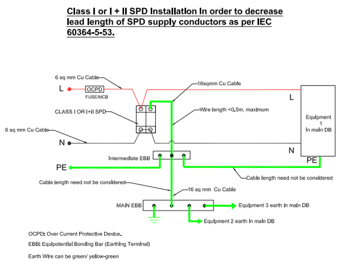
Figure 7- Class I or Class I+II SPD installation to decrease the lead length of SPD supply conductors.
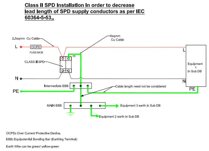
Figure 8- Class II SPD installation to decrease the lead length of SPD supply conductors.
CONCLUSION:
From the above, it is clear that selection & installation of SPD is a Specialist job as the installer shall have thorough knowledge on the current Indian & international standards along with hands-on experience because there are challenges related to each site. Again it is specialised because, most of the panel builders & technicians who install SPDs are conversant with MCB installations & follow the same practice, without reading the “installation manual” of the SPD manufacturer. If the above practices are followed, customers will have years of trouble free operation of their equipment & SPDs.
For more information, contact us at [email protected]"